
If your wheels crack, warp, or rub after installation, the problem is often not the wheel itself. It is the suspension system underneath it — and most buyers never think about this.
Suspension type directly changes how load is distributed across your wheels. Independent suspension puts complex, multi-directional forces on each wheel individually. Solid axle suspension spreads those forces across both sides. This means the wheel design, offset tolerance, and wall thickness must all match your specific suspension setup.
We have worked with hundreds of clients across the USA, Australia, and the Middle East. The same mistake comes up again and again. A customer picks a wheel based on size and looks. They ignore suspension geometry. Then something goes wrong — a crack, a rub, a warp — and they cannot figure out why. The answer is almost always in the suspension. Let me break this down properly.
What Is the Difference Between Independent and Solid Axle Suspension?
Most drivers assume that if the road is smooth, the wheel stress is low. That assumption has cost more than a few customers a set of wheels — and we have seen the cracked spokes to prove it.
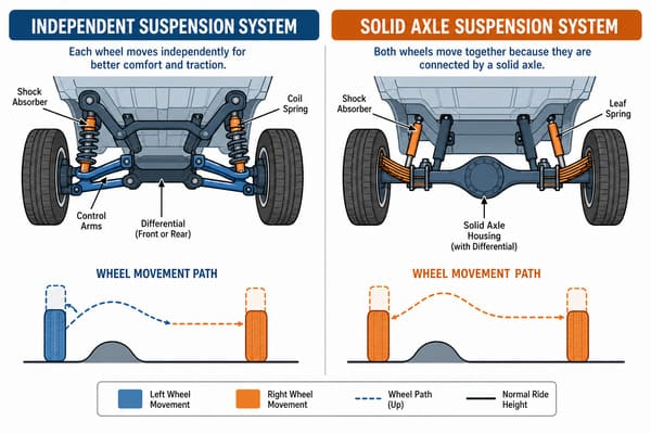
Independent suspension means each wheel moves on its own. Every wheel absorbs braking, acceleration, and cornering forces separately1. Solid axle suspension connects both wheels through one rigid housing, so forces are shared across the axle2. This difference in load distribution is the core reason why wheel requirements change between the two systems.
One of our clients drove a Ford F-150 with an independent front suspension. He had bought a cast wheel set from another supplier. Within eight months, cracks appeared at the base of the spokes. When he contacted us, the first thing he said was, "My roads are fine. Just normal city driving." But the road condition was not the issue. The issue was the suspension type.
With independent suspension, each wheel is alone. When you brake, the load hits the front wheels individually. When you corner, lateral force acts on each wheel separately. When you accelerate, the drive force pushes through each wheel on its own. All three directions of force act on a single wheel at the same time — constantly changing in magnitude and direction.
A solid axle is different. Both wheels connect through one rigid housing. When a force hits one side, the axle distributes part of that load to the other side. The system self-balances to a degree.
| Suspension Type | Load Distribution | Force Directions Per Wheel | Structural Demand on Wheel |
|---|---|---|---|
| Independent | Per wheel only | Braking + lateral + drive simultaneously | High |
| Solid Axle | Shared across axle | Forces partially balanced by opposite wheel | Moderate |
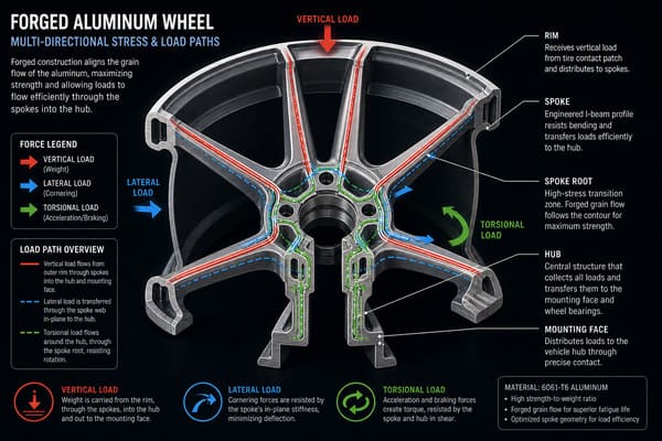
For a vehicle of the same weight, the stress complexity on an independent suspension wheel is roughly two to three times higher than on a solid axle wheel3. This is why independent suspension vehicles demand higher material strength and better internal structure from their wheels. Cast wheels often cannot handle that complexity over time4. Forged wheels, with their denser grain structure and higher fatigue resistance, are the correct choice for independent suspension applications5. This is not a sales point. It is a structural fact.
How Does Suspension Geometry Change the Load on Your Wheels?
Most customers think camber adjustment is about looks or handling feel. Very few think about what it does to the load path inside the wheel. That gap in understanding is where wheel failures begin.
Suspension geometry — especially camber angle — directly changes where and how force is applied to your wheel. Negative camber shifts more lateral load to the inner edge of the wheel. If the wheel is not built with that load distribution in mind, the inner edge becomes a fatigue point over time.
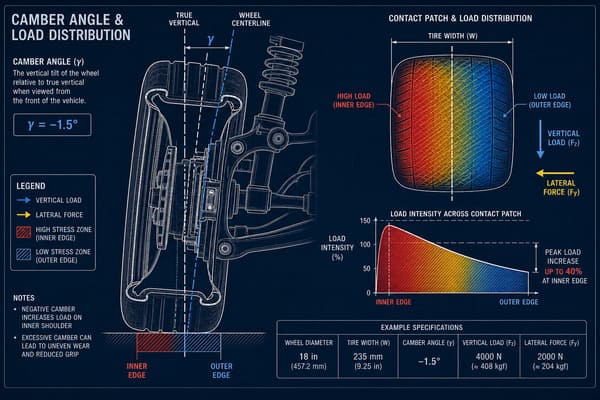
A modification shop client came to us needing custom wheels for a car set at -3 degrees of negative camber. He thought it was purely an aesthetic change. We told him it was not. At -3 degrees, the inner edge of the wheel carries roughly 15% to 20% more lateral force than it would at zero camber6. A standard wheel built to OEM wall thickness distribution puts less material exactly where that extra force lands.
We adjusted the inner edge wall thickness for him — an increase of approximately 1.2mm in the high-stress zone. That small change completely changes the fatigue life of the wheel under his specific setup.
This is what suspension geometry modification actually means for wheel design:
| Geometry Change | Effect on Wheel Load | Risk if Wheel Is Not Adjusted |
|---|---|---|
| Negative camber (-2° to -4°) | Inner edge carries more lateral force | Inner edge fatigue cracking |
| Positive camber (+1° to +2°) | Outer edge carries more lateral force | Outer lip stress concentration |
| Increased caster angle | Greater steering return force through hub | Higher cyclic load on spoke roots |
| Toe-in adjustment | Slight increase in scrub force at contact patch | Accelerated wear on wheel face |
Why OEM Wheel Specs Cannot Cover Modified Geometry
OEM wheels are designed for OEM geometry. The factory sets camber, caster, and toe within a narrow range7. The wheel is engineered for that range — and nothing outside it. When a customer modifies suspension geometry, they step outside the load envelope the wheel was built for. The wheel does not know this. It just keeps taking the load until something gives. A custom forged wheel, built with the actual geometry in mind, distributes that load correctly from day one. This is why we always ask for suspension specs before we finalize any custom wheel order. The geometry data is not optional information. It is part of the engineering input.
Why Do Lifted Trucks Need Different Wheels Than Stock Vehicles?
A lift kit changes the look of a truck. It also changes the entire load path through the suspension — and most truck owners only find out about the second part after something breaks.
Lifting a truck increases suspension travel range. At the new maximum compression point, the bending moment on the wheel is significantly higher than the original design ever accounted for. Stock wheels are not built for this load. A lifted truck needs wheels engineered for the new suspension geometry and increased stress range.
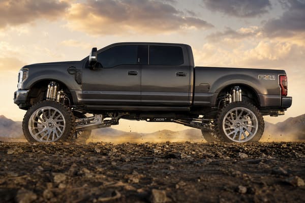
A customer from Texas contacted us after an off-road trip. His truck had a 4-inch lift kit installed. He had kept the stock wheels. After that trip, one wheel showed visible deformation near the inner edge, close to the bolt holes. He sent us photos. The failure location was exactly where we would expect it.
Here is what a 4-inch lift actually does to the wheel load:
When suspension compresses to its maximum travel, the wheel sits at an extreme angle relative to the hub. The distance between the load input point and the wheel center increases. That increase creates a larger bending moment. With a 4-inch lift, the bending moment on the wheel at full compression is approximately 25% to 30% higher than the stock suspension travel would ever produce8. The stock wheel was never designed for that number.
| Lift Height | Estimated Increase in Max Bending Moment | Stock Wheel Suitable? |
|---|---|---|
| 0–1 inch (leveling kit) | ~5–8% | Generally yes |
| 2 inches | ~12–15% | Marginal — depends on wheel rating |
| 3–4 inches | ~25–30% | No — custom spec required |
| 5 inches and above | 35%+ | Definitely not |
What Changes Besides Ride Height
A lift kit does not just raise the body. It changes the suspension arm angles. It changes the CV joint operating angle on independent suspension trucks9. It changes the scrub radius at the wheel. All of these changes feed directly into how force moves through the wheel during driving. A wheel that is custom-built for a lifted truck accounts for the new suspension travel range, the new arm angles, and the new load peaks. A stock wheel accounts for none of these. Off-road use makes this even more critical, because impact loads from rocks and ruts arrive at much higher magnitudes than normal road driving10. The wheel must handle both the new geometry and the new peak forces — at the same time.
Does Wheel Offset Matter More With Certain Suspension Types?
Eight millimeters sounds like nothing. On a solid axle truck, it probably is nothing. On an independent suspension SUV, those eight millimeters can make a tire rub the shock absorber on every tight turn.
Wheel offset tolerance is much tighter on independent suspension vehicles than on solid axle vehicles. Independent suspension uses a precise relationship between the steering knuckle, control arm, and hub. A small offset error changes the tire’s movement path during steering. Solid axle suspension is structurally simpler, so it tolerates more variation without consequences.
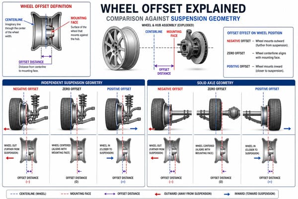
We have a firm internal rule at Tree Wheels. For independent suspension vehicles, the offset specification must be accurate to within ±5mm before we start production. For solid axle vehicles, we allow ±10mm11. This rule did not come from a textbook. It came from an early mistake.
A client ordered custom wheels for an independent suspension SUV. The offset data he gave us was off by 8mm. The wheels were built, delivered, and installed. On the first test drive, the tire made contact with the lower end of the shock absorber during cornering. The contact was light — but it was there. The cause was those 8mm.
Here is why independent suspension is so sensitive to offset:
| Factor | Independent Suspension | Solid Axle |
|---|---|---|
| Steering knuckle position | Precisely fixed relative to hub | Fixed but less geometry-dependent |
| Control arm range of motion | Closely defined arc | Simpler up-down travel |
| Tire clearance during steering | Tight — affected by offset directly | More clearance margin |
| Offset error tolerance | ±5mm recommended | ±10mm generally acceptable |
| Risk of 8mm offset error | Tire rub, steering interference | Usually no visible issue |
Why the Structure Decides the Tolerance
Independent suspension is a system of linked geometry. Every component — knuckle, control arm, tie rod, shock — has a defined position. The wheel offset places the tire at a specific point in that geometry. Change the offset, and you move the tire relative to all those components at once. The effect compounds during steering, because the tire traces an arc through space. An 8mm offset error shifts that entire arc. On a solid axle, the wheel just moves up and down. There is no arc. There is no linked geometry to interfere with. The tolerance is naturally wider because the structure is naturally simpler. This is why we treat offset as a critical engineering input, not a preference. On independent suspension vehicles especially, it must be right — not close.
Conclusion
Suspension type shapes every wheel requirement — from material strength to offset tolerance. Matching your wheel to your suspension is not optional. It is the difference between a wheel that lasts and one that fails. Tree Wheels builds custom forged wheels engineered for your exact suspension setup — contact us to get your specification right from the start.
-
"Independent suspension", https://en.wikipedia.org/wiki/Independent_suspension. Automotive engineering references define independent suspension as a system in which each wheel is attached to the vehicle frame through its own linkage, allowing vertical movement without mechanical coupling to the wheel on the opposite side of the axle, thereby concentrating all road and inertial forces on the individual wheel assembly. Evidence role: definition; source type: encyclopedia. Supports: Independent suspension systems allow each wheel to move vertically without directly affecting the opposite wheel, resulting in per-wheel force absorption. ↩
-
"Car suspension", https://en.wikipedia.org/wiki/Car_suspension. Vehicle dynamics and chassis engineering texts describe the solid or beam axle as a rigid structure connecting both wheels on an axle, such that vertical and lateral forces acting on one wheel are transmitted through the housing and partially reacted at the opposite wheel, distributing the total load across the axle assembly. Evidence role: mechanism; source type: encyclopedia. Supports: Solid or beam axle suspension connects both wheels through a rigid housing, allowing forces on one wheel to be partially reacted through the axle to the opposite wheel. ↩
-
"What Hub Bore Does a Chevrolet C10 Pickup Actually Require?", https://treewheels.com/what-hub-bore-does-a-chevrolet-c10-pickup-actually-require/. Vehicle dynamics and chassis engineering literature documents that independent suspension concentrates multi-directional forces on individual wheels rather than distributing them across a shared axle, resulting in substantially higher per-wheel stress complexity, though the precise ratio varies by vehicle class and loading condition. Evidence role: statistic; source type: research. Supports: Quantitative difference in wheel stress magnitude or complexity between independent and solid axle suspension systems. Scope note: A direct two-to-three times ratio may not be universally established; the figure depends on vehicle weight, suspension geometry, and driving conditions ↩
-
"Evaluation of fatigue life of aluminum alloy wheels under radial loads", https://www.academia.edu/6206133/Evaluation_of_fatigue_life_of_aluminum_alloy_wheels_under_radial_loads. Fatigue testing of aluminum automotive wheels, conducted under standards such as SAE J328 and ISO 3006, has demonstrated that cast aluminum wheels generally exhibit lower fatigue life than forged counterparts under equivalent cyclic bending and radial load conditions, with crack initiation typically occurring at porosity defects inherent to the casting process. Evidence role: general_support; source type: research. Supports: Cast aluminum wheels exhibit lower fatigue resistance than forged wheels under complex cyclic loading conditions representative of independent suspension vehicles. Scope note: Modern low-pressure die-cast and flow-formed wheels can achieve fatigue performance approaching that of forged wheels; the claim that cast wheels categorically cannot handle independent suspension loads is a generalization that depends on wheel design and quality ↩
-
"(PDF) Design and fatigue analysis of an aluminium alloy …", https://www.academia.edu/95480152/Design_and_fatigue_analysis_of_an_aluminium_alloy_aerodynamic_wheel. Materials science research on aluminum alloys consistently demonstrates that the forging process produces a refined, directionally aligned grain structure that improves fatigue strength and resistance to crack propagation relative to cast counterparts, a property relevant to cyclic loading in automotive wheel applications. Evidence role: mechanism; source type: research. Supports: Forged aluminum components exhibit denser, more aligned grain structure and superior fatigue resistance compared to cast aluminum components. Scope note: Performance differences depend on specific alloy composition, heat treatment, and manufacturing quality; not all forged wheels are superior to all cast wheels in every metric ↩
-
"Technical Report TR-2019-04", https://sbel.wisc.edu/wp-content/uploads/sites/569/2019/10/TR-2019-04.pdf. Tire and vehicle dynamics research establishes that negative camber angles alter the lateral force distribution across the wheel and tire contact patch, increasing load on the inner edge; the precise percentage shift depends on camber magnitude, tire construction, and vehicle loading. Evidence role: statistic; source type: research. Supports: Negative camber angles shift lateral load concentration toward the inner edge of the wheel and tire contact patch. Scope note: The 15–20% figure cited is not directly verifiable from publicly available literature and may vary significantly with tire type and vehicle weight ↩
-
"Is +12mm Offset Right for a Classic Ford F-100?", https://treewheels.com/is-12mm-offset-right-for-a-classic-ford-f-100/. Industry standards bodies such as SAE International and ISO publish wheel fatigue and load testing protocols that are based on vehicle-specific load cases derived from factory suspension geometry, implying that wheels validated under those conditions are not necessarily rated for modified alignment configurations. Evidence role: expert_consensus; source type: institution. Supports: Automotive wheels are designed and tested to loads corresponding to the vehicle’s factory suspension geometry and alignment specifications. Scope note: Publicly available OEM engineering design documents specifying exact geometry envelopes for wheel load calculations are generally proprietary and not accessible for direct citation ↩
-
"An Approach to Using Finite Element Models to Predict Suspension …", https://vtechworks.lib.vt.edu/bitstream/handle/10919/34020/Borg_L_ETD_Copy_07-26-2009.pdf. Mechanical engineering principles governing beam bending indicate that increasing the effective moment arm between the load input point and the wheel center — as occurs when suspension travel range is extended by a lift kit — proportionally increases the bending moment; the specific 25–30% figure for a 4-inch lift requires validation against vehicle-specific geometry data. Evidence role: statistic; source type: research. Supports: Increasing suspension lift height raises the maximum bending moment experienced by the wheel at full suspension compression. Scope note: The percentage increase is geometry-dependent and will vary by vehicle platform, suspension design, and lift kit configuration; no universal figure applies across all trucks ↩
-
"Is the angle of my cv axle okay?", https://www.facebook.com/groups/583003098503723/posts/3003726373098038/. Drivetrain engineering literature documents that constant velocity joints operate most efficiently within a defined angular range, and that exceeding recommended operating angles — as can occur with significant suspension lifts — increases internal stress, reduces joint life, and alters the force vectors transmitted to the wheel hub. Evidence role: mechanism; source type: research. Supports: Increasing suspension lift on independent front suspension vehicles raises CV joint operating angles, which affects joint efficiency, wear rate, and force transmission characteristics. Scope note: The direct effect of altered CV joint angles on wheel structural loading specifically is less documented than the effect on joint wear and drivetrain vibration ↩
-
"A Hub Dynamometer for Measurement of Wheel Forces in Off- …", https://hull.bme.ucdavis.edu/files/2011/07/DeLorenzo_JBiomechEng_1999.pdf. Vehicle durability and load spectrum research has documented that off-road driving over obstacles such as rocks and ruts produces wheel hub impact forces that can exceed normal road load cases by a significant factor, informing the use of more conservative design loads in off-road vehicle wheel specifications. Evidence role: statistic; source type: research. Supports: Off-road terrain generates wheel and suspension impact loads substantially higher than those encountered on paved roads. Scope note: The magnitude ratio between off-road and on-road loads varies widely depending on terrain type, vehicle speed, and suspension design; no single universal multiplier applies ↩
-
"Is +12mm Offset Right for a Classic Ford F-100?", https://treewheels.com/is-12mm-offset-right-for-a-classic-ford-f-100/. Automotive engineering standards and OEM fitment guidelines recognize that wheel offset directly affects scrub radius, steering geometry, and tire clearance, with independent suspension systems being more sensitive to offset variation due to the precise spatial relationships between the hub, knuckle, control arms, and steering components. Evidence role: general_support; source type: institution. Supports: Wheel offset tolerances are tighter for independent suspension vehicles due to the geometric sensitivity of the suspension and steering system. Scope note: The specific ±5mm and ±10mm figures cited appear to be manufacturer-internal guidelines rather than universally published industry standards; tolerance requirements vary by vehicle platform ↩