
A wrong wheel fitment can stop your build before it starts. Most buyers check PCD and ET value, but miss the one measurement that causes real problems.
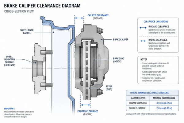
Brake caliper clearance is the physical gap between the inside of your wheel and the outer surface of your brake caliper. You need at least 3mm of clearance, but 5mm is the safe working standard1. If this gap is too small, your wheel will either not fit, rub against the caliper, or affect your braking performance.
Caliper clearance is one of the most overlooked fitment details in wheel upgrades. Most people know to check bolt pattern and offset. Very few people measure the space between their wheel and their brake system before placing an order. This article breaks down exactly what caliper clearance is, how to measure it, what goes wrong when you skip this step, and how much clearance you actually need to stay safe.
What Is Brake Caliper Clearance and Why Does It Matter?
Most buyers send us the right PCD, the right ET value, and the right center bore. Then the wheels arrive and they do not fit. The reason is almost always the same.
Brake caliper clearance is the gap between the inner structure of the wheel — the spoke inner wall and the barrel — and the outer face of the brake caliper. The caliper is fixed. The wheel spins around it. If the gap is not enough, the wheel hits the caliper directly.
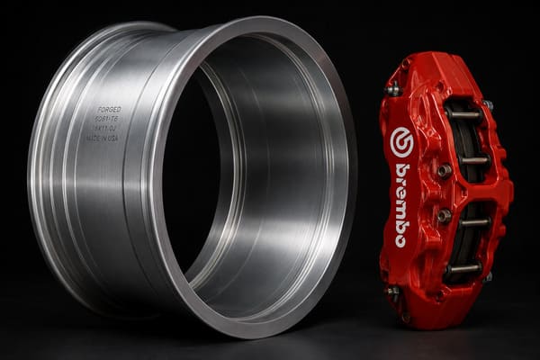
Last year, a customer of ours — a modification shop owner — ordered a set of forged wheels for a Porsche 911 GT3. He sent us the correct vehicle specs, PCD, and ET value. We produced the wheels to standard. When the wheels arrived and he tried to mount them, they would not go on. The reason was simple: he had installed a Brembo six-piston big brake kit. The caliper body was nearly 40% larger than the factory unit. He never mentioned this. The wheels were built to the stock caliper profile, and that profile no longer matched his setup.
This is the core problem with caliper clearance. Many buyers believe that if PCD, ET value, and center bore are correct, the wheel will fit. This is one of the most common misunderstandings we see. PCD controls whether the wheel bolts on. ET value controls how far in or out the wheel sits. Neither of these parameters has anything to do with the caliper.
Caliper size varies a lot between setups. A standard single-piston caliper on a regular passenger car might measure around 80mm tall and 90mm wide. A performance four-piston aftermarket caliper can exceed 120mm in height and 150mm in width2. On the same car, a brake system upgrade completely changes the caliper profile.
This is why, for every custom order we receive, we ask: has your brake system been upgraded? Not just what car it is. The vehicle model tells us the factory caliper. It tells us nothing about what the customer actually has installed.
Forged wheels have a real advantage here. We can control the inner geometry of the spoke design and adjust the barrel depth to create more room for large calipers. But we can only do this if we know the caliper dimensions. Without that information, there is no way to build the right clearance into the design.
| Setup Type | Typical Caliper Height | Typical Caliper Width |
|---|---|---|
| Stock single-piston | ~80mm | ~90mm |
| Aftermarket 4-piston | ~110mm | ~130mm |
| Big brake 6-piston | 120mm+ | 150mm+ |
How Do You Measure Brake Caliper Clearance Before Buying New Wheels?
Sending us a vehicle model is not enough when you have an upgraded brake system. The data we need comes from the actual caliper installed on your car, not from a factory spec sheet.
To measure brake caliper clearance, you need two numbers: the radial clearance (distance from wheel center to the top of the caliper) and the axial clearance (distance from the rotor hat face to the outermost face of the caliper). These two measurements let us confirm fitment during the 3D modeling stage.
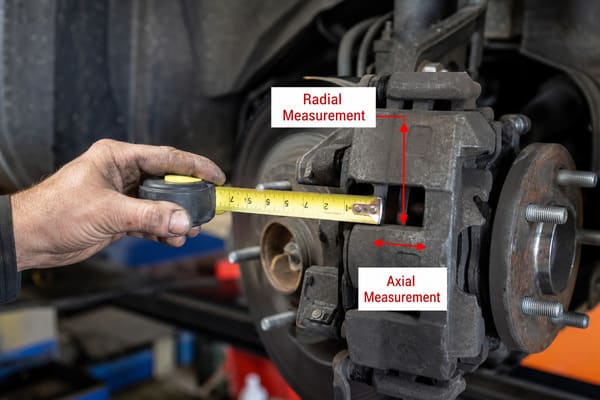
One of our long-term B2B customers in Australia runs a modification shop. Every time they place an order, they send us one photo: a tape measure next to the caliper with two numbers written on it. One number is the radial distance from the wheel center to the highest point of the caliper. The other is the axial distance from the rotor hat flange to the outermost face of the caliper. With those two numbers, we can verify clearance directly in the 3D model before we cut a single piece of metal. It is a simple method, and it works.
Here is how each measurement works in practice:
Radial Clearance — How Tall Is Your Caliper?
Radial clearance is measured from the center of the wheel hub outward to the highest point of the caliper body. This number controls how wide and how far outward the spokes can be designed. If the spokes start too far out toward the rim, they will contact the top of the caliper. For customers without professional tools, we recommend cutting a piece of cardboard to match the wheel inner diameter, marking approximate spoke positions, and holding it up against the caliper. This is not a precise measurement, but it will show obvious clearance problems immediately.
Axial Clearance — How Deep Can the Barrel Go?
Axial clearance is measured from the face of the rotor hat flange to the outermost face of the caliper. This number controls how deep the inner barrel can go. If the barrel is too deep, the inner wall will press against the side of the caliper. For our B2B clients, we recommend a digital caliper accurate to 0.1mm. Send us the measurement, and we overlay it onto the 3D model at no extra cost. This is part of our standard process.
One Detail Most People Miss
Measurements should always be taken with the car sitting at normal ride height and under normal load. An unloaded car and a fully loaded car will have slightly different caliper positions relative to the hub. The difference is usually 1 to 2mm. If your clearance is already tight, that 1 to 2mm is the difference between a safe fit and a contact problem.
| Measurement | What It Controls | Recommended Tool |
|---|---|---|
| Radial clearance | Spoke width and starting position | Tape measure or digital caliper |
| Axial clearance | Barrel depth | Digital caliper (0.1mm accuracy) |
| Load condition | Real-world gap accuracy | Measure at normal ride height |
What Happens If Your Wheels Don’t Clear the Brake Calipers?
Most people think a clearance problem means the wheel simply won’t go on. In reality, clearance problems come in three levels, and the most dangerous one is the hardest to notice.
If your wheels do not clear the brake calipers, you will face one of three outcomes: the wheel cannot be mounted at all, the wheel rubs against the caliper during driving and causes noise or vibration, or the caliper loses its floating range and produces uneven brake pad wear and longer stopping distances.
We rank these three outcomes by how dangerous they are, not by how common they are.
Level One: The Wheel Will Not Mount
This is the best possible outcome. The wheel goes onto the hub and immediately something is wrong — the lug nuts won’t seat properly, the wheel sits at an angle, or it simply will not push far enough to mount. You know right away. The only loss is time and shipping cost. There is no safety risk because the vehicle never moves.
Level Two: The Wheel Mounts but Rubs During Driving
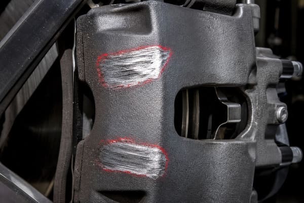
This is far more dangerous. At rest, there is just enough clearance for the wheel to sit in position. But when the suspension compresses under load, or when the wheel deflects slightly under cornering forces, the inner spoke begins to make periodic contact with the caliper. The driver hears a low-frequency knocking or clicking sound, or feels light vibration through the steering wheel. One of our customers came to us with this exact problem. He had been driving nearly 3,000 kilometers before he noticed anything serious. When we looked at the wheel, the caliper housing had two clear friction lines across it, and the inner spoke had lost a strip of its surface coating3. He had no idea this was happening.
Level Three: Caliper Function Is Restricted
This is the hardest to detect because it develops slowly. Brake calipers need a small amount of float to apply equal pressure from both sides of the rotor. If the inner barrel wall presses against the caliper housing and limits that float, one brake pad will wear faster than the other. Over time, braking distance increases and the car pulls to one side under braking. By the time the driver notices, the brake system has already been compromised for a long time4.
| Failure Level | Symptom | Safety Risk |
|---|---|---|
| Level 1: Will not mount | Visible misfit at installation | None — caught immediately |
| Level 2: Intermittent contact | Noise, vibration during driving | Medium — physical damage to wheel and caliper |
| Level 3: Caliper float restricted | Uneven pad wear, brake pull | High — brake performance affected |
This is exactly why we provide 3D model confirmation and sample production before full orders go into production. A responsible forged wheel manufacturer should never skip this step.
How Much Clearance Do You Need Between a Wheel and a Caliper?
Three millimeters is the number most people quote. It is technically the minimum, but using it as your working target is a mistake. The gap that looks safe on paper is often much smaller in real conditions.
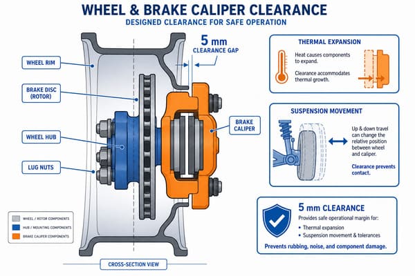
The industry-accepted minimum clearance between a wheel and a brake caliper is 3mm. However, the recommended working standard is 5mm. This accounts for heat expansion of the caliper, suspension movement during driving, and the cumulative effect of manufacturing tolerances across multiple components.
There are three specific reasons why 3mm is not enough as a working target, and each one has real numbers behind it.
Reason One: Thermal Expansion
Brake calipers generate significant heat during use. Under normal road driving, caliper temperatures reach 150°C to 200°C. On a track or under aggressive driving conditions, they can exceed 400°C5. Aluminum alloy calipers have a thermal expansion coefficient of approximately 23 μm per meter per degree Celsius6. A caliper that is 150mm wide and heats up by 200°C will expand by nearly 0.7mm7. That sounds small, but if your static clearance is 3mm, your effective working clearance is already down to 2.3mm before any other factors are considered.
Reason Two: Suspension Movement
As the vehicle moves over uneven surfaces, the suspension compresses and rebounds. This produces a small relative movement between the wheel and the caliper. On most production vehicles, this movement range is between 0.5mm and 1.5mm8. On sport-tuned vehicles or cars with aftermarket stiff springs, the number can be larger. This movement must fit within whatever clearance remains after thermal expansion is already accounted for.
Reason Three: Stacked Manufacturing Tolerances
The wheel itself carries a production tolerance, typically ±0.2mm to ±0.5mm9. The brake rotor has its own tolerance. The wheel bearing has its own operating play. When all of these tolerances combine in the worst direction at the same time, the total can exceed 1mm. This is not a failure — it is normal variation within acceptable manufacturing ranges. But it still consumes clearance.
| Factor | Estimated Clearance Consumed |
|---|---|
| Thermal expansion (200°C rise) | ~0.7mm |
| Suspension movement | 0.5mm – 1.5mm |
| Stacked manufacturing tolerances | up to ~1mm |
| Total reduction from 3mm nominal | up to 3.2mm |
A nominal 3mm clearance, under real working conditions, may leave less than 1mm of true margin. This is why we use 5mm as our internal working standard.
For our three-piece forged wheels, the inner barrel depth can be adjusted independently without changing the outer rim design or the ET value10. This means that when a customer has a large brake kit installed, we can increase the inner clearance without touching the appearance or the offset of the wheel. This is one of the most practical customization advantages that forged wheels have over cast wheels — and it is only possible when the customer gives us the caliper dimensions upfront.
Conclusion
Caliper clearance is not a small detail. It affects safety, fitment, and brake performance. Measure before you order, and target 5mm — not 3mm. At Tree Wheels, we build every custom forged wheel with your exact brake setup in mind, so fitment is confirmed before production ever starts.
-
"Cal Poly BSAE Brake Caliper", https://digitalcommons.calpoly.edu/cgi/viewcontent.cgi?filename=1&article=1899&context=mesp&type=additional. Automotive engineering standards bodies such as SAE International or OEM service documentation typically define minimum wheel-to-caliper clearance thresholds; the specific values cited here should be verified against an applicable technical standard or manufacturer specification. Evidence role: expert_consensus; source type: institution. Supports: Minimum and recommended clearance values between wheel inner barrel and brake caliper. Scope note: A single universal published standard for this exact clearance value may not exist; OEM values can vary by vehicle platform and brake system design ↩
-
"Single vs Two Piston Brake Caliper Comparison", https://www.youtube.com/watch?v=r2GcGGFoqZY. Brake system supplier documentation and automotive engineering references indicate that aftermarket high-performance calipers are substantially larger than OEM single-piston units; specific dimensional data should be verified against manufacturer specifications for the relevant brake kit. Evidence role: general_support; source type: other. Supports: Approximate physical dimensions of single-piston OEM versus multi-piston aftermarket brake calipers. Scope note: Caliper dimensions vary widely by manufacturer, vehicle platform, and product generation; the figures presented are approximate ranges rather than universal specifications ↩
-
"Is my wheel making contact with my brake caliper? : r/AskMechanics", https://www.reddit.com/r/AskMechanics/comments/1lsnt5t/is_my_wheel_making_contact_with_my_brake_caliper/. Automotive service documentation and wheel fitment guidance from manufacturers and inspection bodies describe intermittent spoke-to-caliper contact as a known failure mode that produces visible wear marks on caliper housings and wheel interior surfaces, and may go undetected by the driver for extended periods. Evidence role: case_reference; source type: other. Supports: Physical abrasion damage resulting from intermittent contact between wheel inner spokes and brake caliper housing during driving. Scope note: The case cited is a single anecdotal account from a commercial context; independent documentation of this specific failure pattern from neutral technical sources would strengthen the claim ↩
-
"Tribological and performance assessment of two wheeler …", https://pmc.ncbi.nlm.nih.gov/articles/PMC12479935/. Brake system engineering literature and vehicle safety research document that impedance of floating caliper movement results in asymmetric pad contact, accelerated one-sided pad wear, and directional brake pull, with potential increase in stopping distance under repeated brake application (see, e.g., NHTSA technical reports on brake system performance). Evidence role: mechanism; source type: research. Supports: Restriction of floating caliper lateral movement leads to uneven brake pad wear and degraded braking performance. Scope note: Quantified stopping distance increases resulting specifically from caliper clearance restriction are not extensively reported in open literature; the severity of performance degradation depends on the degree of restriction and vehicle braking system design ↩
-
"Experimental Study of Automotive Brake System …", https://www.wsdot.wa.gov/research/reports/fullreports/434.1.pdf. Brake system thermal studies, including those published in SAE technical papers (e.g., SAE 2003-01-3313 on brake thermal performance), report caliper and rotor temperatures consistent with the ranges cited; temperatures during track driving are noted as potentially exceeding 400°C depending on brake system design and duty cycle. Evidence role: statistic; source type: research. Supports: Brake caliper operating temperature ranges under normal and aggressive driving conditions. Scope note: Temperature values vary significantly by vehicle type, brake system design, driving intensity, and measurement location on the caliper ↩
-
"Thermal expansion", https://en.wikipedia.org/wiki/Thermal_expansion. The thermal expansion coefficient of aluminum alloys is widely cited in materials engineering references as approximately 23 μm/m/°C; see, e.g., the relevant entry in Wikipedia’s ‘Thermal expansion’ article or standard materials handbooks such as ASM Aerospace Specification Metals. Evidence role: definition; source type: encyclopedia. Supports: The thermal expansion coefficient of aluminum alloys is approximately 23 μm per meter per degree Celsius. Scope note: The exact coefficient varies slightly by alloy composition; 23 μm/m/°C represents a general value for common aluminum alloys rather than a specification for any particular caliper material ↩
-
"Thermal expansion", https://en.wikipedia.org/wiki/Thermal_expansion. Applying the standard linear thermal expansion formula ΔL = α·L·ΔT with α ≈ 23 × 10⁻⁶ /°C for aluminum alloy, L = 0.150 m, and ΔT = 200°C yields ΔL ≈ 0.69 mm, consistent with the figure cited; this formula and aluminum coefficient are described in standard physics and engineering thermodynamics textbooks (see, e.g., Çengel & Boles, Thermodynamics: An Engineering Approach). Evidence role: mechanism; source type: education. Supports: Calculated linear thermal expansion of a 150mm aluminum component subjected to a 200°C temperature rise using the standard linear expansion formula ΔL = α × L × ΔT. Scope note: The calculation assumes uniform temperature distribution across the caliper body and uses a representative aluminum coefficient; actual expansion will differ based on caliper alloy composition and non-uniform heating ↩
-
"suspension and steering middterm Flashcards", https://quizlet.com/ca/669995109/suspension-and-steering-middterm-flash-cards/. Vehicle dynamics and suspension engineering literature describes relative movement between wheel hub components under load as a function of suspension geometry and compliance; the cited 0.5–1.5mm range represents a commonly applied design allowance, though published empirical ranges vary by vehicle class and suspension type. Evidence role: mechanism; source type: research. Supports: The magnitude of relative movement between wheel and caliper caused by suspension compression and rebound. Scope note: This figure is presented as a typical range but no specific engineering study or OEM specification is cited; actual values depend heavily on suspension design, vehicle weight, and spring rate ↩
-
"Interpretation ID: 86-1.39", https://www.nhtsa.gov/interpretations/86-139. Wheel dimensional tolerances are governed by standards such as the Japan Light Alloy Wheel (JWL) specification and ISO 4249; production tolerances for alloy wheels typically fall within ranges consistent with those cited, though exact permissible deviations depend on wheel size, material, and the specific dimensional parameter being measured. Evidence role: definition; source type: institution. Supports: Manufacturing dimensional tolerances applicable to road wheels. Scope note: The cited tolerance range applies to the wheel as a whole; individual manufacturing standards specify tolerances for distinct dimensions such as runout, bolt circle, and center bore separately ↩
-
"What Are the Current Design Trends in Premium Forged Wheels?", https://treewheels.com/what-are-the-current-design-trends-in-premium-forged-wheels/. Wheel manufacturing references and aftermarket wheel industry documentation describe three-piece wheel construction — comprising outer lip, center disc, and inner barrel assembled with fasteners — as inherently allowing barrel depth and offset adjustments without altering the center disc or outer rim profile; this is a recognized design characteristic of the three-piece format. Evidence role: general_support; source type: other. Supports: Three-piece wheel construction allows the inner barrel depth to be modified independently of the outer rim profile and wheel offset. Scope note: The degree of adjustability varies by manufacturer design; not all three-piece wheels offer unlimited barrel depth customization, and structural integrity requirements impose limits on barrel depth changes ↩