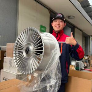

Every wheel looks finished on the outside. But most people have no idea what happens before the paint goes on. The gap between a rough forged blank and a finished wheel is where everything matters.
CNC machining is the process that turns a rough forged aluminum blank into a precision wheel.1 It cuts the spoke profiles, bolt holes, and mounting face to tolerances as tight as ±0.02mm2. Without CNC, a forged blank cannot meet the dimensional accuracy required for safe installation.

I have been working in forged wheel production for years, and the most common misunderstanding I hear is that forging and CNC are competing processes. They are not. They are two steps in the same chain. If either one is missing or done poorly, the wheel fails. In the sections below, I will walk through exactly what CNC does at each stage, how long it takes, what parts of the wheel it touches, and why the question of "CNC vs. forged" is the wrong question to ask.
What Role Does CNC Machining Play in Forging a Wheel Blank?
A forged blank just came out of the press. It looks like a metal disc. The surface is rough, covered in oxidation, and the dimensional tolerance is around ±2mm. That is not a wheel yet. That is raw material.
CNC machining takes a forged blank through two lathe operations and one milling stage. The first lathe pass cuts the outer diameter and face. The second cuts the inner cavity and back profile. After both passes, tolerance tightens to ±0.3mm. CNC milling then cuts spoke shapes, the mounting face, and bolt holes to a final tolerance within ±0.02mm.

The three steps are not interchangeable. Forging gives the wheel its internal strength by compressing the grain structure of the aluminum.3 The lathe operations give it basic dimensional shape. CNC milling gives it final precision and the visual profile the customer actually sees. Remove any one of the three and the wheel is incomplete.
I want to share something that happened in our own production line. We received a batch of 80 forged blanks from a supplier. Their forging temperature control was unstable, which caused uneven internal density. After the first lathe pass, fine delamination lines appeared on the surface. We rejected the entire batch on the spot. None of those 80 blanks moved to the next operation. We sent them all back.
That decision cost us time. But sending a structurally compromised blank through CNC milling and then out to a customer is not something we are willing to do. The forging quality has to be right before CNC machining can do its job.
What Happens at Each Stage?
| Stage | Operation | Tolerance Achieved |
|---|---|---|
| Forged Blank | Press forming | ±2.0mm |
| First Lathe Pass | Outer diameter and face | ±0.3mm |
| Second Lathe Pass | Inner cavity and back profile | ±0.3mm |
| CNC Milling | Spokes, mounting face, bolt holes | ±0.02mm |
Each stage depends on the one before it. If the forged blank has internal defects, the lathe passes will expose them.4 If the lathe passes are skipped or rushed, the CNC milling program cannot hold its reference points. The sequence is fixed for a reason.
How Long Does It Take to CNC a Wheel?
Customers sometimes ask why a one-piece forged wheel takes 15 to 20 days when CNC machining itself only takes a few hours. That is a fair question, and the answer is in the full production chain, not just the CNC step.
CNC milling one wheel takes 2 to 4 hours depending on spoke count and design complexity.5 More spokes mean longer tool paths and more time. But the full lead time for a one-piece forged wheel is 15 to 20 days because CNC is one step inside a longer sequence that includes lathe work, inspection, cleaning, and surface treatment.

Here is the full sequence we follow for every order. After the forged blanks arrive, the first and second lathe passes take 1 to 2 days. CNC milling takes 2 to 4 hours per wheel. After milling, every wheel goes through coordinate measuring machine inspection6, which takes about half a day. Cleaning takes 1 to 2 hours. Surface treatment varies by finish: powder coating takes 1 day, anodizing takes 2 to 3 days, and electroplating takes 3 to 5 days7. Every one of these steps happens in our own facility.
Lead Time Breakdown by Surface Treatment
| Surface Treatment | Estimated Time |
|---|---|
| Powder Coating | 1 day |
| Anodizing | 2–3 days |
| Electroplating | 3–5 days |
A customer once ordered 4 wheels and asked about shipping on day 3. I told him the CNC was done and the wheels were in anodizing. He asked if we could switch to powder coating to save time. I said yes, but the color result would be different. He thought about it and said to keep the anodizing. The wheels shipped on day 12. He told me the color looked better than he expected. That is what happens when you do not cut the process short.
What Is CNC on Wheels?
When people ask what CNC does on a wheel, they usually picture the spoke design. That is the most visible part. But the spoke profile is actually the least demanding of the three main CNC operations on a forged wheel.
CNC machining on a forged wheel focuses on three areas: the mounting face, the bolt holes, and the spoke profiles. The mounting face requires flatness within ±0.02mm. Bolt holes require both diameter and position accuracy. Spoke profiles require ±0.1mm, which is the most relaxed tolerance of the three.

The mounting face is the flat surface on the back of the wheel that contacts the hub flange. A human hair is approximately 0.07mm thick.8 The mounting face tolerance we hold is ±0.02mm, which is more than three times finer than a single hair. If the mounting face is off, the wheel will not sit flat against the hub.9 At highway speed, that causes steering wheel vibration.10 In serious cases, it affects driving safety.
Tolerance Requirements by CNC Zone
| CNC Zone | Tolerance Requirement | Consequence of Failure |
|---|---|---|
| Mounting Face | ±0.02mm | Vibration, unsafe installation |
| Bolt Holes | ±0.1mm diameter and position | Loose fastening, long-term loosening risk |
| Spoke Profiles | ±0.1mm | Visual inconsistency |
Bolt holes have two separate requirements. The diameter must be accurate, and the position of each hole relative to the center must be accurate at the same time. If the diameter is off by more than 0.1mm, the bolt will not torque correctly.11 Over time, it can loosen during driving.12
We had a batch of 32 eighteen-inch wheels that failed the final inspection before shipping. The mounting face deviation was 0.05mm, which is outside our acceptable range. All 32 wheels went back for rework. The customer waited two extra days. We did not ship wheels with a mounting face that was out of tolerance. That is not a decision we negotiate on.
Is CNC Better Than Forged?
This question comes up often, and it points to a real confusion in the market. CNC is a machining method. Forging is a forming method. They do not belong in the same comparison.
CNC machining and forging are not alternatives to each other. Forging builds internal strength by compressing the aluminum grain structure. CNC machining builds dimensional precision by removing material. A forged wheel without proper CNC machining lacks accuracy. A CNC-machined wheel without a forged blank lacks strength. Both are required.

The tensile strength of a forged aluminum wheel is typically above 310MPa. A cast aluminum wheel sits around 200 to 230MPa. That difference comes entirely from the forging process. CNC machining cannot change the internal grain structure of a metal blank. It removes material. It does not compress it.
Forging vs. CNC: What Each Contributes
| Property | Forging Contributes | CNC Contributes |
|---|---|---|
| Internal strength | Yes | No |
| Grain structure density | Yes | No |
| Mounting face flatness | No | Yes |
| Bolt hole precision | No | Yes |
| Spoke profile and design | No | Yes |
| Final dimensional accuracy | No | Yes |
The market has two common problems. The first is wheels marketed as "CNC precision machined" where the blank is actually cast, not forged. The casting process does not compress the grain structure. The strength is not there, regardless of how precise the machining is. The second is wheels marketed as "forged" where the post-forging machining is rough. The mounting face is uneven. The wheel vibrates when installed.
Every wheel we produce goes through the complete sequence. We source forged blanks that have passed heat treatment and ultrasonic flaw detection. We run the first and second lathe passes in-house. We do the CNC milling in-house. We run coordinate measuring machine inspection, cleaning, and surface treatment, all in our own facility. This is not a choice between forging and CNC. Both answers are required, and we do not skip either one.
Conclusion
CNC machining and forging are not competing options. They are two parts of the same process. One builds strength. The other builds precision. A finished wheel needs both.
At Tree Wheels, every forged wheel goes through the full production chain, in-house, with no shortcuts. Explore our custom forged wheel options at TreeWheels.
-
"[PDF] CNC machining: The complete engineering guide", https://gab.wallawalla.edu/~ralph.stirling/classes/engr480/examples/nvx/NVX/Helpful%20Docs/CNC_Machining_The_Complete_Engineering_Guide.pdf. A neutral manufacturing reference on CNC machining can support that CNC is a subtractive, computer-controlled process used to produce precise final geometry from a rough metal workpiece. Evidence role: definition; source type: education. Supports: CNC machining turns a rough forged aluminum blank into a precision wheel by removing material under computer control.. Scope note: This would support the machining principle generally, not the specific workflow or tolerances of this manufacturer. ↩
-
"[PDF] Design, specification and tolerancing of micrometer-tolerance …", https://nvlpubs.nist.gov/nistpubs/Legacy/IR/nistir5615.pdf. A manufacturing-metrology or CNC machining source can document that modern CNC machining and inspection systems can achieve micrometer-scale dimensional tolerances under controlled conditions. Evidence role: general_support; source type: research. Supports: CNC machining can achieve very tight dimensional tolerances, such as ±0.02 mm, in controlled production contexts.. Scope note: Such a source would show that this tolerance range is technically plausible, but it would not independently verify the author’s specific wheel-production tolerance. ↩
-
"(PDF) Effect of Multidirectional Forging on the Grain Structure and …", https://www.academia.edu/74102776/Effect_of_Multidirectional_Forging_on_the_Grain_Structure_and_Mechanical_Properties_of_the_Al_Mg_Mn_Alloy. A materials-engineering source on forging can support that plastic deformation during forging refines or aligns grain structure and can improve mechanical properties compared with as-cast metal. Evidence role: mechanism; source type: education. Supports: Forging improves aluminum wheel strength by plastically deforming and refining or aligning the metal grain structure.. Scope note: The source would explain the metallurgical mechanism generally; wheel-specific performance depends on alloy, heat treatment, and process control. ↩
-
"[PDF] Understanding Geometrical Forging Defects – Mines Files", http://wpfiles.mines.edu/wp-content/uploads/aspprc/ResearchMaterials/Publications/337-Van-Tyne.pdf. A source on machining forged or cast components can support that subsurface discontinuities such as laps, inclusions, or delaminations may become visible when material is removed during machining. Evidence role: mechanism; source type: paper. Supports: Machining operations can reveal internal or subsurface defects in forged blanks.. Scope note: The evidence would support the general inspection mechanism, not the specific batch-rejection incident described in the article. ↩
-
"Mill Toolpath Guide – Purdue University", https://www.purdue.edu/bidc/resources/metal-working/mill-toolpath-guide/. A CNC machining source discussing toolpath length, feature complexity, and cycle time can support that more complex geometries require longer machining time. Evidence role: mechanism; source type: education. Supports: CNC milling time increases with spoke count and design complexity because more complex geometry requires longer toolpaths and machining operations.. Scope note: The 2–4 hour duration appears to be process-specific and would likely need internal production records; an external source can only support why complexity affects cycle time. ↩
-
"Dimensional Measurement Services | NIST", https://www.nist.gov/programs-projects/dimensional-measurement-services. A metrology reference can support that coordinate measuring machines are used to measure three-dimensional part geometry and verify dimensional tolerances in manufacturing. Evidence role: definition; source type: institution. Supports: Coordinate measuring machines are used to inspect machined wheels or components for dimensional conformity.. Scope note: This supports the inspection method generally, not the specific half-day inspection time stated for the author’s production line. ↩
-
"[PDF] Metal Finishing Processes – Rochester Institute of Technology", https://www.rit.edu/affiliate/nysp2i/sites/rit.edu.affiliate.nysp2i/files/docs/resources/Metal_Finishing_Processes_Best_Practices.pdf. Technical sources on anodizing and electroplating can support that these are multi-step surface-finishing processes involving cleaning, surface preparation, treatment, rinsing, and post-treatment operations. Evidence role: mechanism; source type: institution. Supports: Anodizing and electroplating require multiple surface-preparation and treatment steps, contributing to longer production lead times.. Scope note: External sources can justify why these finishes take longer than simple machining, but they may not confirm the exact 2–3 day or 3–5 day lead times for this facility. ↩
-
"Hair’s breadth – Wikipedia", https://en.wikipedia.org/wiki/Hair%27s_breadth. A scientific or educational reference on human hair diameter can support that typical scalp hair diameters are on the order of tens of micrometers, commonly around 70 micrometers. Evidence role: statistic; source type: education. Supports: A typical human hair is approximately 0.07 mm in diameter.. Scope note: Hair diameter varies substantially by individual, ethnicity, and measurement method, so the value is an approximate comparison rather than a fixed constant. ↩
-
"[PDF] Wheel-End Maintenance Procedures – nhtsa", https://static.nhtsa.gov/odi/tsbs/2018/MC-10138462-9999.pdf. An automotive engineering or service reference can support that wheel-to-hub mating surfaces must be flat and clean to ensure proper seating and clamping of the wheel assembly. Evidence role: mechanism; source type: institution. Supports: An inaccurate or uneven wheel mounting face can prevent the wheel from seating properly against the hub flange.. Scope note: Such a source would support the fitment principle, while the exact allowable mounting-face deviation may be governed by manufacturer specifications or wheel standards. ↩
-
"[PDF] A STUDY OF PARAMETERS INFLUENCING THE VEHICLE WHEEL …", https://ninercommons.charlotte.edu/record/746/files/Patel_uncc_0694N_11115.pdf. An automotive engineering source on wheel runout and imbalance can support that wheel or hub mounting irregularities may cause vibration that becomes noticeable at vehicle speeds. Evidence role: mechanism; source type: institution. Supports: Improper wheel seating or mounting-face irregularity can contribute to steering wheel vibration at speed.. Scope note: The source would support a common causal pathway for vibration; actual vibration diagnosis can involve tires, suspension, balance, and other factors. ↩
-
"How do you calculate clamping force from bolt torque? – Reddit", https://www.reddit.com/r/AskEngineers/comments/182badp/how_do_you_calculate_clamping_force_from_bolt/. A fastener-engineering or wheel-installation reference can support that wheel fastener clamping depends on correct hole geometry, seating, and torque application. Evidence role: mechanism; source type: institution. Supports: Incorrect bolt-hole geometry can interfere with proper wheel fastener seating and torque/clamp load.. Scope note: The specific 0.1 mm threshold may be a manufacturer tolerance and may not be directly confirmed by general fastener literature. ↩
-
"[PDF] Part 573 Safety Recall Report 23V-283 | NHTSA", https://static.nhtsa.gov/odi/rcl/2023/RCLRPT-23V283-6242.PDF. A transportation-safety or fastener reference can support that insufficient wheel fastener clamp load or improper installation can lead to progressive loosening during vehicle operation. Evidence role: mechanism; source type: government. Supports: Improper wheel fastener seating or torque can increase the risk of wheel fasteners loosening during driving.. Scope note: The source would support the general loosening risk; it would not prove that every 0.1 mm bolt-hole deviation produces loosening. ↩